Makita EA3201S Spezifikationen
Stöbern Sie online oder laden Sie Spezifikationen nach Kraftkettensägen Makita EA3201S herunter. Makita EA3201S Specifications Benutzerhandbuch
- Seite / 15
- Inhaltsverzeichnis
- LESEZEICHEN
Inhaltsverzeichnis
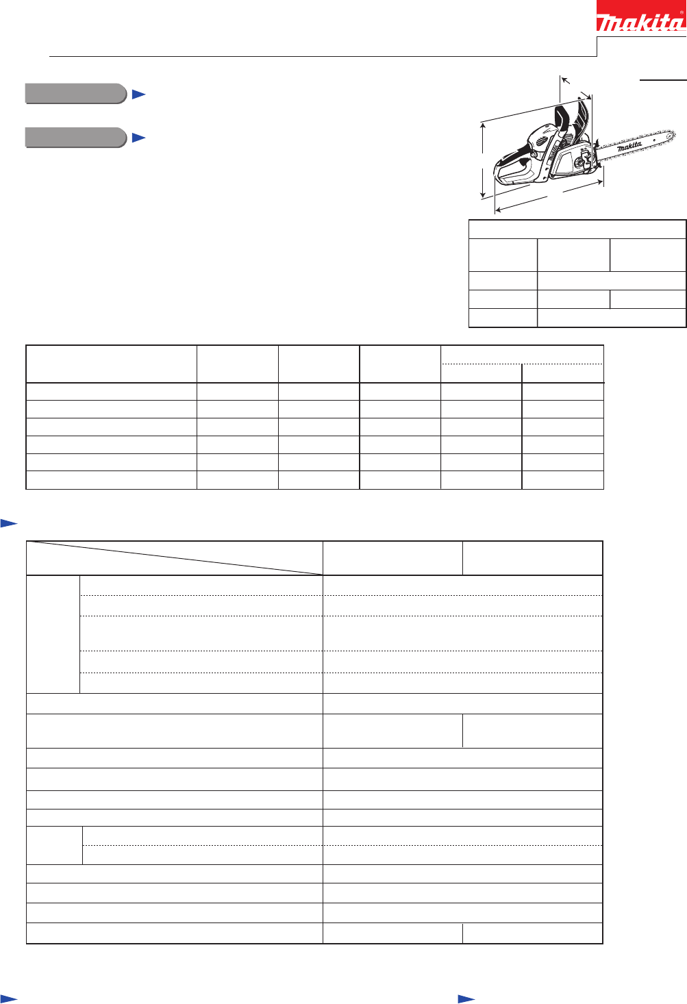
PRODUCTCONCEPT AND MAIN APPLICATIONSP 1/ 15 SpecificationStandard equipmentNote: The standard equipment for the tool shown above may vary by country.
P 10/ 15(2) Check the following points. • Intermediate flange is inserted into the groove on Engine housing complete. • When Cylind
P 11/ 15See Figs. 27 and 28 for the positions of Needle-idle (L) and Needle-high speed (H) . After tightening each Needle to the full;• unscrew Needl
P 12/ 15Unscrew 5.5x16 Hexalobular tapping screw and pull Grip shell halfslightly up and toward the screw hole side. (Fig. 31) Note: When disassemblin
P 13/ 15(1) Referring to “DISASSEMBLY of [2]-11. Tank assembly”, disassemble the machine as drawn in Figs. 33 and 32.(2) Using long-nose pliers, caref
P 14/ 15(1) Remove “Air filter, Carburetor, and Intermediate flange” as mentioned in [2]-10. (Figs. 21, 22, 23, and 24)(2) Piston set can be separated
P 15/ 15Repair[3] FASTENING TORQUEFastening forCrank case underside 266608-2 45x40 Hexalobular tapping screw Part No. of Screw/ Bolt/ Clutch Descripti
P 2/ 15[1] NECESSARY REPAIRING TOOLS[2] DISASSM|BLY/ ASSEMBLY[2]-1. Chain tensionerDescriptionCode No. Use forT-type hexalobular wrench (1) Remove Sp
P 3/ 15(1) Remove Sprocket guard, Guide bar and Saw chain from machine.(2) Insert Small-slotted screwdriver into the gap between Crank shaft and Reta
P 4/ 15(1) Remove Sprocket guard, Guide bar and Saw chain from machine.(2) Remove Clutch drum assembly. (Figs. 4 and 5) (3) Turn Hand guard toward C
P 5/ 15(1) Remove Sprocket guard, Guide bar and Saw chain from machine.(2) Unscrew M5x40 Hexalobular socket head bolt and two M5x16 Hexalobular socke
P 6/ 15(1) Remove Sprocket guard, Guide bar and Saw chain from machine.(2) Pull Hand guard toward Tubular handle to release Chain brake. Then, remove
P 7/ 15(1) Remove Clutch drum section and Clutch section. Refer to [2]-2 “Clutch drum section” and [2]-5 “Clutch section”. (2) Remove Tension s
P 8/ 15(1) Remove Sprocket guard, Guide bar and Saw chain from the machine.(2) Remove “Recoil starter section”. See [2]-7.(3) Remove Spark plug and
P 9/ 15Note: Drain Fuel tank before disassembling Carburetor. See Fig. 21. (1) Remove Hood. (2) Turn Choke lever to the position
Verwandte Produkte und Handbücher für Kraftkettensägen Makita EA3201S
 (20 Seiten)
 (66 Seiten)
(20 Seiten)
(66 Seiten)
(20 Seiten)


 (120 Seiten)
 (40 Seiten)

 (128 Seiten)
 (20 Seiten) (40 Seiten)
© 2020, manymanuals.de. Alle Rechte vorbehalten. | 1.433 s |
 Manymanuals.com
 Manymanuals.de
 Manymanuals.fr
 Manymanuals.it
 Manymanuals.pl
 Manymanuals.cz
 Manymanuals.es
 Manymanuals-pt.com
Kommentare zu diesen Handbüchern