Makita BHR162 Bedienungsanleitung
Stöbern Sie online oder laden Sie Bedienungsanleitung nach Rotationshämmer Makita BHR162 herunter. Repair - Makita Benutzerhandbuch
- Seite / 12
- Inhaltsverzeichnis
- LESEZEICHEN
- Specification 1
- Standard equipment 1
- Optional accessories 1
- ECHNICAL INFORMATION 1
- [1] NECESSARY REPAIRING TOOLS 2
- P 2 / 12 2
- [2] LUBRICATION 2
- Ring spring 19 3
- P 4 / 12 4
- [3] DISASSEMBLY/ASSEMBLY 4
- [3] -2. Armature 4
- P 5 / 12 5
- [3] -2. Armature (cont.) 5
- [3] -3. Gear Section 5
- P 6 / 12 6
- P 7 / 12 7
- [3] -3. Gear Section (cont.) 7
- P 8 / 12 8
- P 9 / 12 9
- [3] -5. Tool Holder Section 9
- [Correct] [Wrong] 10
- Circuit diagram 11
- Wiring diagram 12
Inhaltsverzeichnis
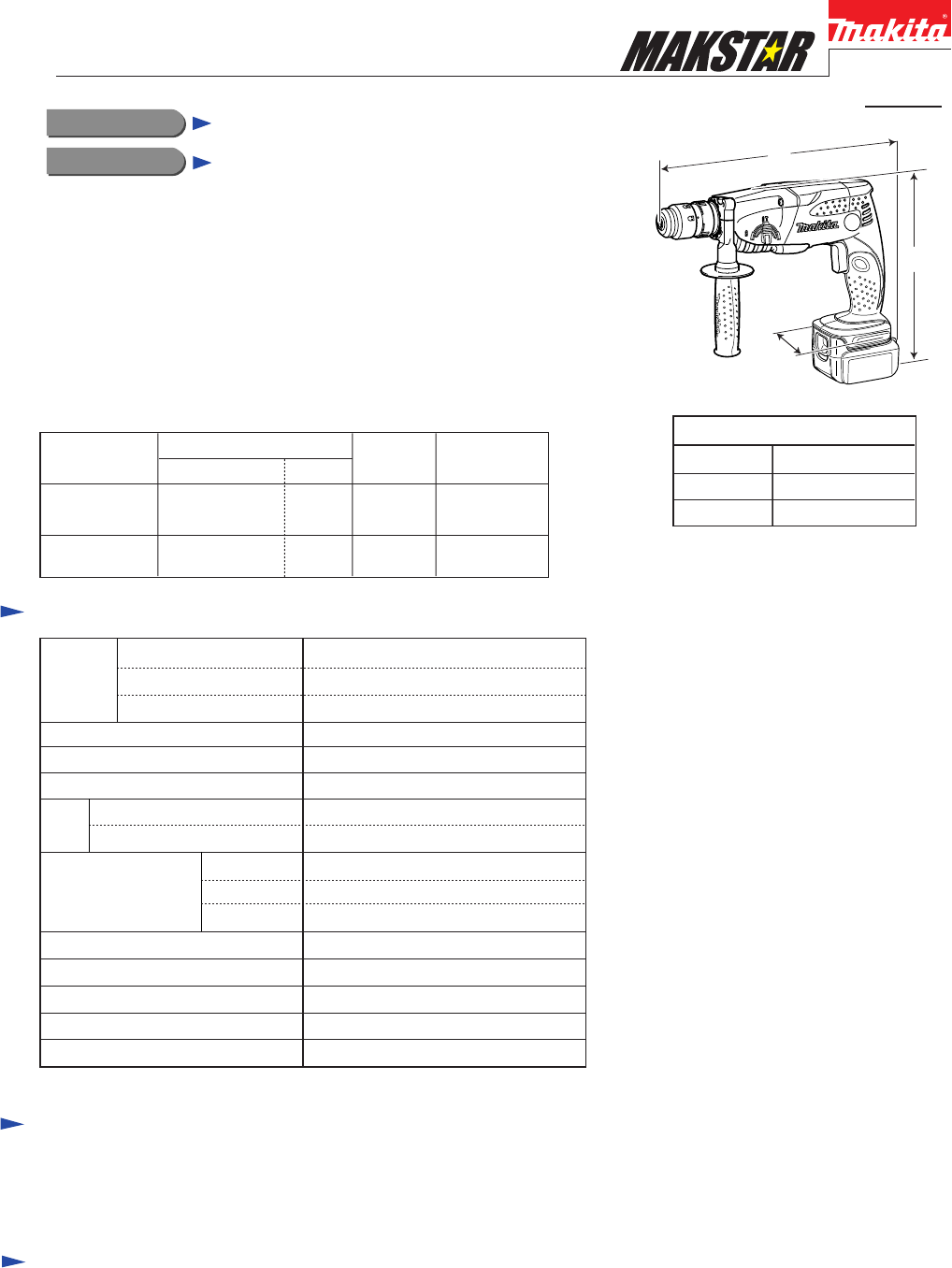
Model No. DescriptionPRODUCTCONCEPT AND MAIN APPLICATIONS P 1 / 12SpecificationStandard equipmentDimensions: mm (")Width (W)Height (H)Length (L)2
P 10/ 12Repair[3] DISASSEMBLY/ASSEMBLY1) Install X ring 13 on Impact bolt. Assemble Ring 11 to Impact bolt as illustrated to left in Fig. 33.2)
Circuit diagramP 11/ 12Color index of lead wires' sheathBlackRedOrangeBlueYellowYoke UnitFETEndbellSwitchLight CircuitConnectorTerminalFig. 38LED
Wiring diagramP 12/ 12Connectorlead wire holderlead wire holderlead wire holderLEDConnecting terminalribTerminal sideSwitch sideWith the lead wire (or
P 2 / 12Repair[2] LUBRICATIONApply the following kinds of grease to protect parts and product from unusual abrasion, when repairing or changing carbon
P 3 / 12Repair[3] DISASSEMBLY/ASSEMBLY[3] -1. Tool Holder Fig. 3Fig. 4DISASSEMBLINGCap 35Ring spring 191R003Ring 211) After taking off Cap 35, remove
P 4 / 12Repair[3] DISASSEMBLY/ASSEMBLY[3] -2. ArmatureFig. 7 Fig. 8Fig. 10 Fig. 11 Fig. 12DISASSEMBLINGLock buttonChange leverChange lever positioneda
P 5 / 12Repair[3] DISASSEMBLY/ASSEMBLY[3] -2. Armature (cont.)Do the reverse of the disassembling steps.ASSEMBLING[3] -3. Gear SectionFig. 13Fig. 14 F
P 6 / 12Repair[3] DISASSEMBLY/ASSEMBLY[3] -3. Gear SectionFig. 17Fig. 18 Fig. 20Fig. 19DISASSEMBLINGASSEMBLINGFig. 16 9) Remove Ball bearing 606ZZ fr
P 7 / 12Repair[3] DISASSEMBLY/ASSEMBLY[3] -3. Gear Section (cont.)ASSEMBLING7) Assemble Ball bearing 606ZZ, Oil seal 25 and Ball bearing 6805LLB to Ge
P 8 / 12Repair[3] DISASSEMBLY/ASSEMBLY[3] -4. Inner Housing CompleteFig. 23 Fig. 24 Fig. 25DISASSEMBLINGCompression spring 3Change plateStopper plateP
P 9 / 12Repair[3] DISASSEMBLY/ASSEMBLY[3] -4. Inner Housing Complete (cont.)Fig. 27 Fig. 282) Mount Compression spring 3 in place by connecting one en
Weitere Dokumente für Rotationshämmer Makita BHR162

Verwandte Produkte und Handbücher für Rotationshämmer Makita BHR162


 (72 Seiten)
 (12 Seiten)
(12 Seiten)
(12 Seiten)

 (17 Seiten)


 (72 Seiten)
 (60 Seiten)
(12 Seiten)
(16 Seiten)
(16 Seiten)
(16 Seiten)
(60 Seiten)
(12 Seiten)
(16 Seiten)
(16 Seiten)
(16 Seiten)
© 2020, manymanuals.de. Alle Rechte vorbehalten. | 0.395 s |
 Manymanuals.com
 Manymanuals.de
 Manymanuals.fr
 Manymanuals.it
 Manymanuals.pl
 Manymanuals.cz
 Manymanuals.es
 Manymanuals-pt.com
Kommentare zu diesen Handbüchern